Portable workstations are high-performance laptops that allow professionals to run applications such as photo and video editing, gaming, 3D rendering, CAD/CAM tasks and more. Such devices, equipped with power-hungry CPUs and GPUs, require a power supply unit (PSU) in the range of 300 W to 500 W. The design of such a PSU is intrinsically difficult because of space and thickness constraints that require high power densities. Other applications with similar power requirements include wide-screen OLED TVs, as well as desktops that integrate the main computer components—CPU, monitor and speakers—into a single sleek unit.
In a paper presented at APEC in February 2024, Navitas Semiconductor showcased a converter prototype with LLC topology converting 400 V DC to 24 V DC. The converter module sports a profile of only 8 mm with a remarkable power density (21.5 kW/L). Peak efficiency is 98.1%, whereas full-load efficiency (400 W) reaches 97.4%.
400-W converter topology
The 400-W PSU for such devices, such as the one found inside Apple’s Studio Display, usually consists of two stages. The power-factor-correction (PFC) boost circuit converts AC voltage from the mains to 380 V DC. The second stage is an isolated LLC DC/DC converter in a half-bridge configuration producing regulated voltages of 20 V and 24 V. The typical circuit implementing this power converter is shown in Figure 1.
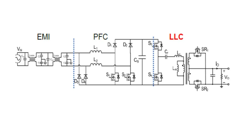
Figure 1: Topology of two-stage power converter
To achieve a good tradeoff between efficiency and EMI emissions, the boost PFC is operated at a 65-kHz switching frequency. Conversely, the LLC resonant converter can switch at a near-150-kHz frequency because of reduced switching losses.
GaN is the right technology
The commercial availability of GaN transistors has made it possible to increase the switching speed of power converters. Consequently, planar transformers can easily be integrated onto PCBs with a significant size reduction of the magnetics. It is also possible to integrate the resonant inductor into the transformer, with further gains in terms of miniaturization. Planar transformers and planar inductors are designed with flat, layered structures instead of traditional wound wire coils.
Building a high-efficiency and high-density LLC converter can be facilitated by using Navitas’s proprietary GaNFast half-bridge ICs with GaNSense. The components include two GaN FETs and drivers plus control, level shifters, a bootstrap (to power up the high-side switch), sensing and protection housed in a low-profile, thermally enhanced 6 × 8-mm QFN package. Figure 2 gives more details on the package pinout and cooling pads.
High-side I/O pins include the high-side IC supply pins, and low-side I/O pins include PWM inputs, dV/dt turn-on control and current-sensing output. The low-side source pad with I/O pins is separated from the high-side source pad with I/O pins by a proper high-voltage creepage distance. The heat generated from GaN transistors is evacuated through source cooling pads at the bottom side of the QFN package to the PCB. Large PCB copper areas and thermal vias are then used to conduct the heat to the opposite side of the PCB and/or to more layers that have large copper planes, where it can then be spread out.
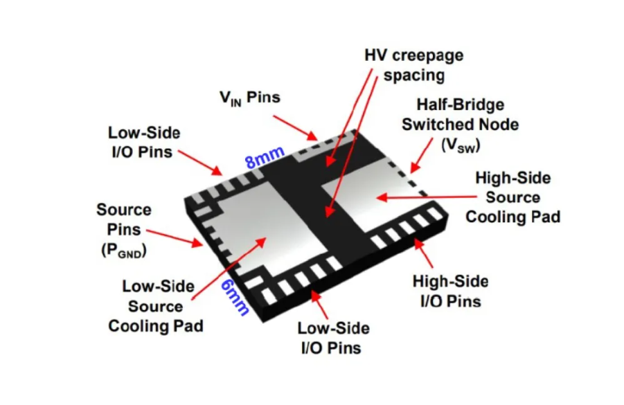
Figure 2: Navitas GaN half-bridge IC
Operation of resonant LLC converter
From Figure 1, we can see that the LLC section consists of a half-bridge, resonant tank circuit, transformer and rectifier network that is realized with synchronous rectifier (SR) FETs instead of diodes for improved efficiency and driving. The two switches of the half-bridge are turned on with a 50% duty cycle (in reality, a dead time is allowed to avoid any risk of shoot-through); therefore, a square wave is generated at the input of the resonant tank, which acts as a filter to produce a sine wave of the fundamental frequency. The sine wave is then transferred to the secondary side through the high-frequency transformer, which scales the voltage down. Finally, the SRs convert the sine wave into a stable DC output. The LLC converter’s efficiency is achieved by the resonant tank’s capability to allow soft switching and reduce switching losses.
Figure 3 depicts a schematic of the resonant tank, made by resonant capacitor Cr, resonantinductor Lr, magnetizing inductance Lm and AC equivalent load RAC. The LLC converter has a wide range of operation and high efficiency owing to two resonance frequencies: fr1 = 1 ÷ [2p√(LrCr)] and fr2 = 1 ÷ [2p√(Lr + Lm)Cr], with fr1 > fr2. When frequency f > fr1, the input impedance of the loaded resonant tank is inductive, whereas for f < fr2, the input impedance is capacitive. In the frequency region fr2 < f < fr1, the impedance can be either inductive or capacitive depending on the load resistance R. The LLC resonant converter normally operates in the region where the input impedance of the resonant tank is inductive; i.e., it increases with frequency. This implies that power flow can be controlled by varying the converter’s operating frequency so that a reduced power demand from the load causes the frequency to rise, while an increased power demand produces a frequency reduction.
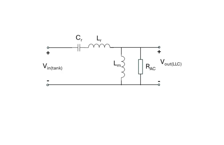
Figure 3: Equivalent schematic of resonant tank. RAC is the AC equivalent load resistance.
Magnetic design
The matrix transformer is a good solution for PCB-based planar transformers. A matrix transformer is composed of a number of smaller “elements” inter-wired in a matrix. Elements with small cross-sections result in low-profile transformers that can handle high power. Small elements are also more efficient in removing heat and easier in being heatsinked. The name “matrix transformer” originates from its initial configuration, which had rows and columns. A matrix transformer with four columns and three rows can give an effective turns ratio of 4:3.
The equivalent reluctance model of a matrix transformer for a resonant LLC design is quite complex, but relatively straightforward equations allow the calculation of Lr—equal to the leakage inductance of the integrated magnetic structure—and Lm. Furthermore, a modified version of the matrix transformer can be obtained that lowers flux density in the core plate compared with the conventional matrix transformer. In the modified arrangement, the flux density of the core plate is distributed across the whole plate and therefore becomes much lower. Consequently, the core loss is drastically reduced, while at the same time, the thickness of the plates gets smaller.
The converter module, tested at 500 kHz and 400-W output power with thermal management, is highly integrated in that it contains a half-bridge NV6247 IC together with Cr, output SR and output capacitors, so it only needs a PWM signal and power source to function. A creepage distance of 7 mm minimum ensures safety even for practical use. The power converter can also provide 300 W with natural convection. The module's size is 62.5 x 37.2 x 8 mm and its power density reaches 21.5 kW/L (0.35 kW/in.3).
About US
Heisener Electronic is a famous international One Stop Purchasing Service Provider of Electronic Components. Based on the concept of Customer-orientation and Innovation, a good process control system, professional management team, advanced inventory management technology, we can provide one-stop electronic component supporting services that Heisener is the preferred partner for all the enterprises and research institutions.